Stage 1/6: Soldering the Freader Board
The Freader board is straightforward to assemble and solder, and should take around around 1 to 2 hours to complete depending on soldering expertise.
For those with no soldering experience, we recommend viewing training videos on YouTube, and you might consider purchasing a practice soldering board (example here) before moving on to the assembly of the Freader board. You should also familiarise yourself with the health and safety risks of soldering — take adequate precautions to protect yourself and never breath in solder fumes.
The Freader kit includes all the parts needed to assemble a single Freader board apart from AA rechargeable batteries and the Adafruit HUZZAH breakout board, a ready-made part that performs the role of broadcasting data from the Freader over WiFi to the Raspberry Pi server (Stage 3). Do shop around for the best price for the Adafruit board, though we have found Pimoroni to be a competitive and reliable retailer.
Below is a list of all the parts, tools and accessaries that we recommend to assemble the Freader board.
Parts included in the kit
Freader board (green)
RFID circuit board (yellow)
One 100pf capacitor
One 10uF capacitor
Four 1.8nF capacitors
Two 10nF capacitors
Four 100nF capacitors
One 2.2uF capacitor
Two 1k resistors (colour bands brown, black, red, gold)
One 10 ohm resistor (colour bands brown, black, black, brown)
1 Level shifter
Header pins
RFID coil cable connection terminal
Battery holder
Header Jumper
Parts not included in the kit
Tools and Accessories
Soldering iron
Solder
Wire cutter / side cutter
Blu Tack or similar
Instructions
1.1 Make sure you’ve got everything by laying it all out on the printable sheet provided here
1.2 Place the two 8 pin headers in the underside of the yellow RFID circuit board (the opposite side to one labelled ‘Top’). Ensure that the shorter side of the header pins are placed into the board, leaving the longer pins exposed.
1.3 Carefully place the yellow circuit board (and the headers) into the holes labelled RFID on the main green circuit board in the position above. Make sure the orientation of the yellow board is exactly as in this image.
1.4 Solder the 16 header pins that pass through the yellow board to the yellow board itself.
1.5 Once you have soldered the header pins to the yellow board, use Blu Tack or similar to temporary hold the board in place, then flip the green board over to work on the underside.
1.6 Solder the 16 pins that pass through the green board to the green board itself.


1.7 Cut six pins off of the long row of header pins and place them in the row of holes on the short edge of the top of the blue Adafruit HAZZAH circuit board with the longer side of the pin pointing upwards. These pins will point outwards from the board and will be used to register / program the board in Stage 3. Hold them in place with the Blu Tack.
1.8 Flip over the blue circuit board and solder the six header pins to the underside of the board.
1.9 Cut two rows of ten header pins from the long row and place these in the underside of the blue board, with the longer length of the pins pointing downwards.
1.10 Place the blue board into the green circuit board. Be sure to match its position to the one indicated in the photo above. Solder the header pins to the blue circuit board, then hold in place with Blu Tack.
1.11 Flip the board over and solder the pins from the blue board onto the underside of the green board.
1.12 Find the level shifter integrated circuit (IC) that looks like a rectangular box.


1.13 Gently roll the legs on the flat surface to straighten the legs (see before and after photos).
1.14 Place the level shifter IC into position. Make sure the indent / circular notch of the IC (left hand side in image) matches the indent on the white lines printed on the green board.


1.15 Blu Tack in place, flip over the green board and solder the legs in place.
1.16 Find the two 1k resistors (colour bands brown, black, red, gold).
1.17 Bend the legs of both resistors as shown.


1.18 Place the first resistor all the way into the holes (labelled 1K), then flip over the green board and bend the legs as shown. Note: Resistors do not have a specific polarity so they can be placed either way around.


1.19 Solder legs in place and remove excess leg with the sidecutters.


1.20 Place second resistor and repeat process.


1.21 Find 10 ohm resistor (blue resistor) and bend legs as before.
1.22 Place in position (labelled 10 ohm) and repeat process of the previous resistors. Remember to trim the legs on the underside after soldering.

1.23 Cut a row of two header pins from the long row of header pins.


1.24 Place it in the two holes between the blue board and the printed word ‘mynaturewatch.net’ on the green board, with the longer pins pointing up. Blu Tack this in place and the flip over the green board to solder in place.

1.25 Find the 1.8nF Capacitors (labelled 182J in very small lettering).
1.26 Place in positions as shown. Note that these capacitors do not have a specific polarity and can be placed in either direction.
1.27 Blu Tack in position and flip over. Bend the legs away from each other as with the resistors.
1.28 Solder in place and trim the excess legs with side cutters.
1.29 Find the 100pF capacitor. It will be labelled 101 on the side and be the only one in the kit of its size and type (don’t get it confused with any of the other capacitors, though). Note: this capacitor does not have a specific polarity.


1.30 Place in position as shown above. Flip the board, bend the legs to it in position, then solder in place and trim the excess legs.
1.31 Find the 10μF Capacitor, it will be clearly marked with 10μF on the side. The longest leg is the positive terminal of the capacitor.

1.32 Place in position as shown above (there are two places on the board for these type of capacitor and this one is the one closest to the yellow circuit board). Make sure the longest leg goes into the positive hole (marked with a plus symbol on the board) and the negative in the side marked with a white semi circle.

1.33 Blu Tack in place and solder the underside. Trim the excess legs when soldered.

1.34 Find the two 10nF capacitors. They will be marked with 103 on the side (in tiny lettering). They do not have a polarity and can be place either way around.

1.35 Place them in the position shown above. Flip the board, bend the legs to hold them in position, then solder in place and trim the excess legs.

1.36 Find the four 100nF capacitors (will be marked with 104 on the side).

1.37 Place in the position shown above, they do not have a polarity and can be placed either way around.
1.38 Bend the legs to hold the capacitors in place, solder, then remove excess legs.

1.39 Find the 2.2μF capacitor, it will be clearly marked with 2.2μf on the side. The longest leg is the positive terminal of the capacitor.
1.40 Place in position as shown above (there are two places on the board for these type of capacitor, the other has already been soldered and this one is the one closest to the blue circuit board). Make sure the longest leg goes into the positive hole (marked with a plus symbol on the board) and the negative in the side marked with a white semi circle.
1.41 Flip the board, bend the legs, solder in place and remove excess legs.

1.42 Find the RFID coil cable connector terminal.


1.43 Place in position as shown above.


1.44 Flip over the board and bend the legs down, then solder in place.


1.45 Trim off any excess legs on any components. The pins from the blue circuit board are likely to protrude the most.
1.46 Find the battery holder.
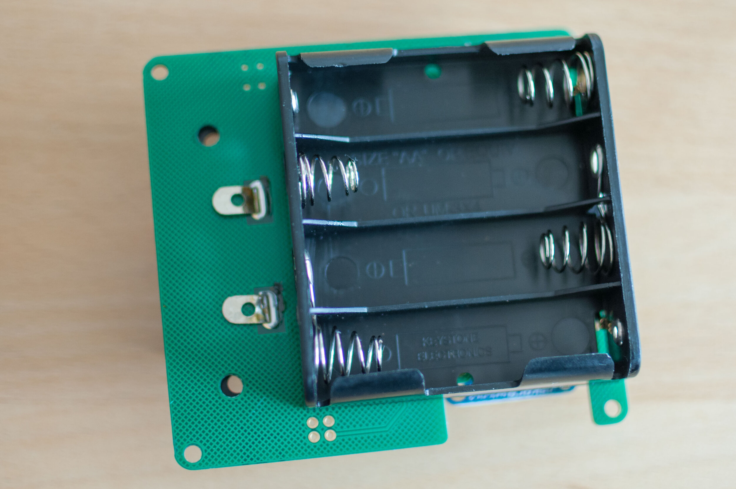

1.47 Place in position as shown above.


1.48 Flip over and solder, then trim the excess legs.


1.49 Find the header jumper and place on the row of two header pins next to the blue circuit board.
1.50 Congratulations, you’ve now completed Stage 1/6 ‘Soldering the Freader Board’.
When you’re ready please move onto Stage 2/6 ‘Building the Freader Hardware’.