MyNaturewatch Camera: Raspberry Pi Model 3A+ Adaptation

 
01.JPG

Lorem ipsum dolor sit amet, consectetur adipiscing elit, sed do eiusmod tempor incididunt ut labore et dolore magna aliqua. Ut enim ad minim veniam, quis nostrud exercitation ullamco laboris nisi ut aliquip ex ea commodo consequat. Duis aute irure dolor in reprehenderit in voluptate velit esse cillum dolore eu fugiat nulla pariatur. Excepteur sint occaecat cupidatat non proident, sunt in culpa qui officia deserunt mollit anim id est laborum.

02.JPG

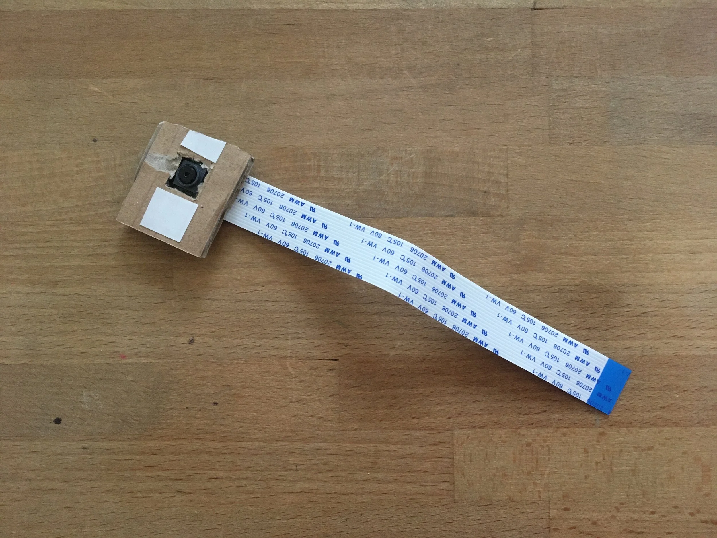
1. Cut a rectangular piece of cardboard slightly taller and quite a bit longer than the camera module. Cut a small camera lense sized square in the middle. Using double sided tape stick this to the front of the camera module. Then add more tape to the top of the cardboard, but leave it unpeeled for now.

03.JPG

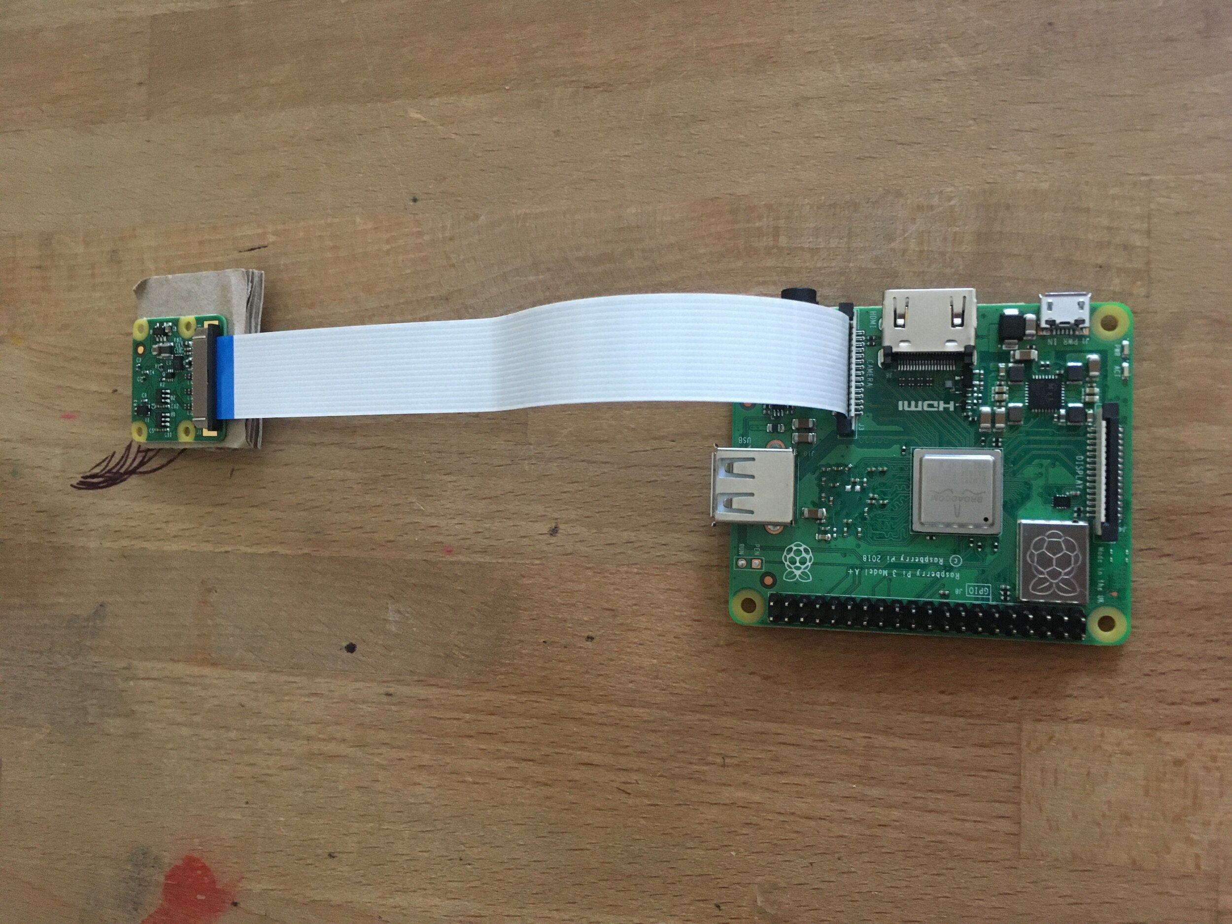
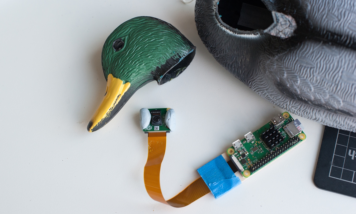
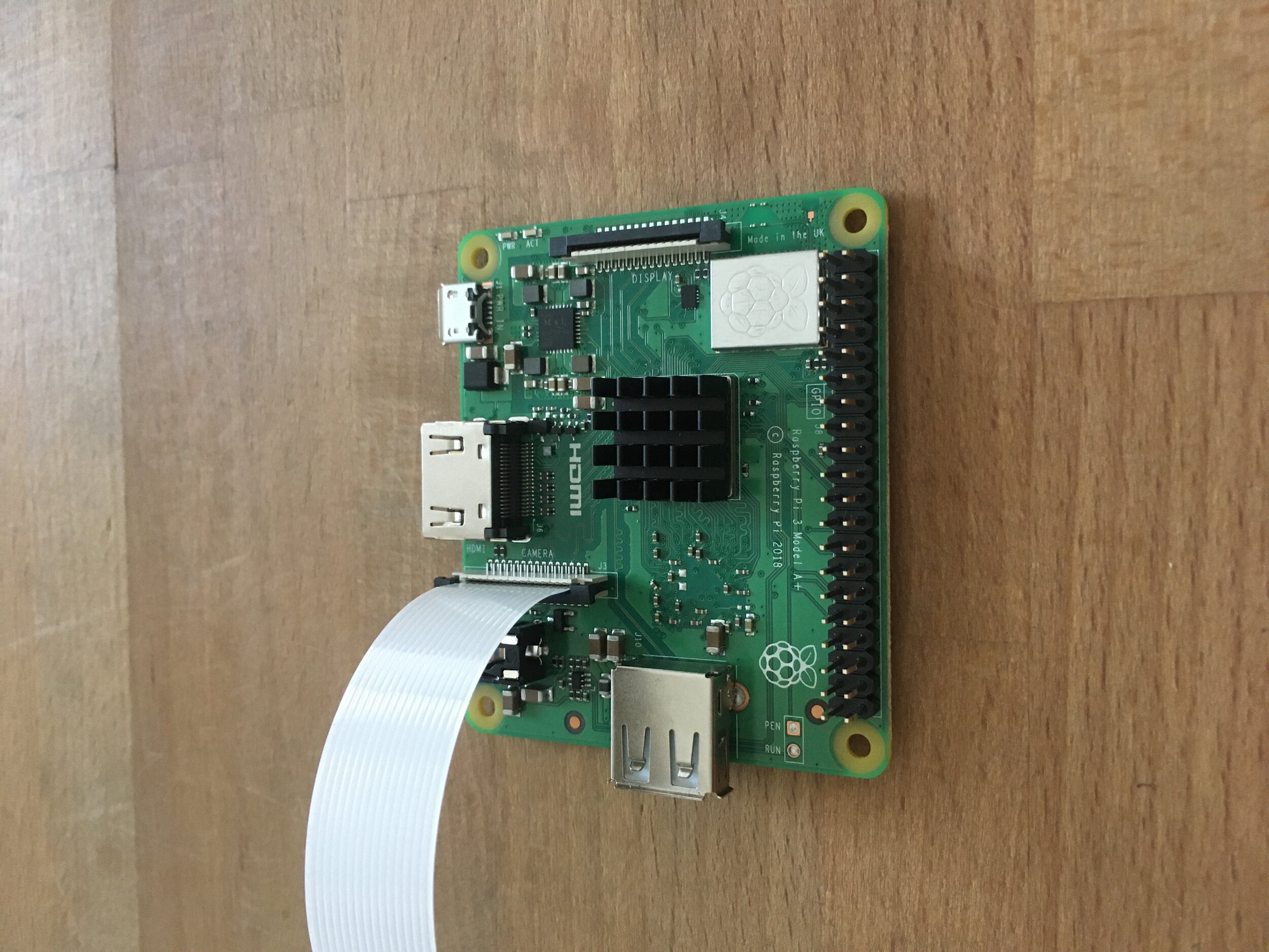
2. Connect the camera ribbon to the Raspberry Pi 3A+ via the narrow connector named ‘Camera’ and making sure it’s the correct way round as shown. Lock the Ribbon by pushing down on the black thingy.

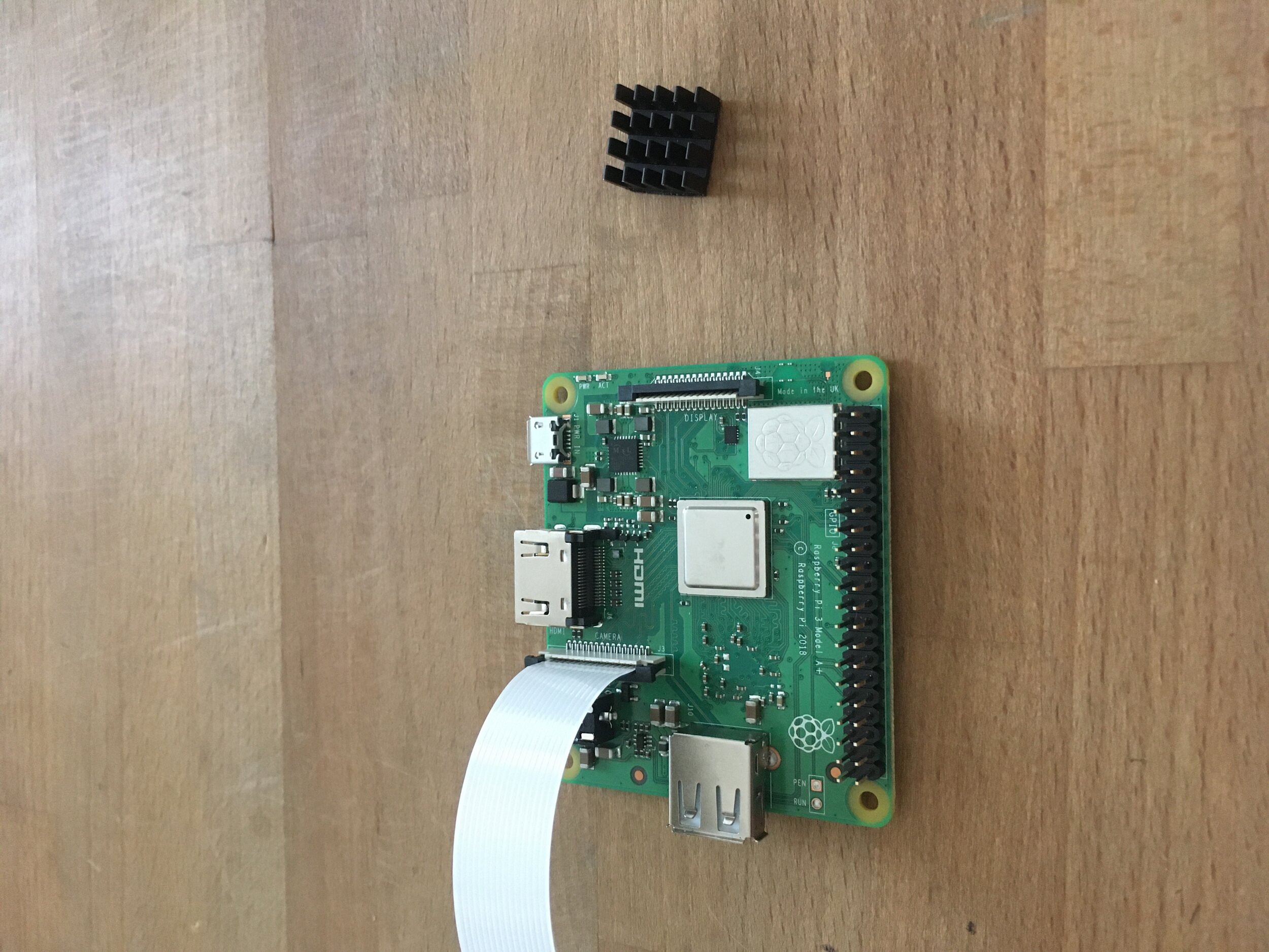
3. Add the Heat Sink….

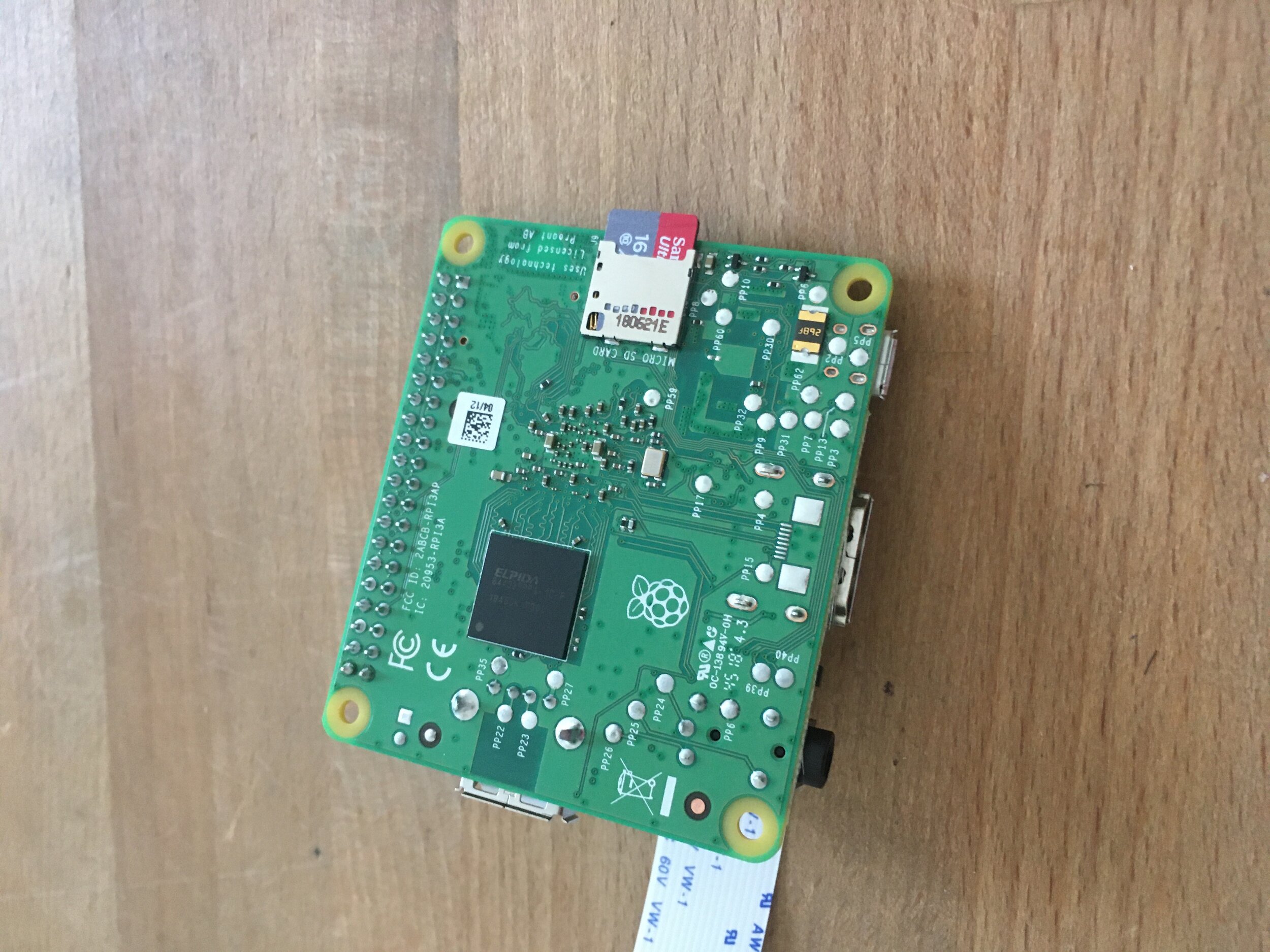
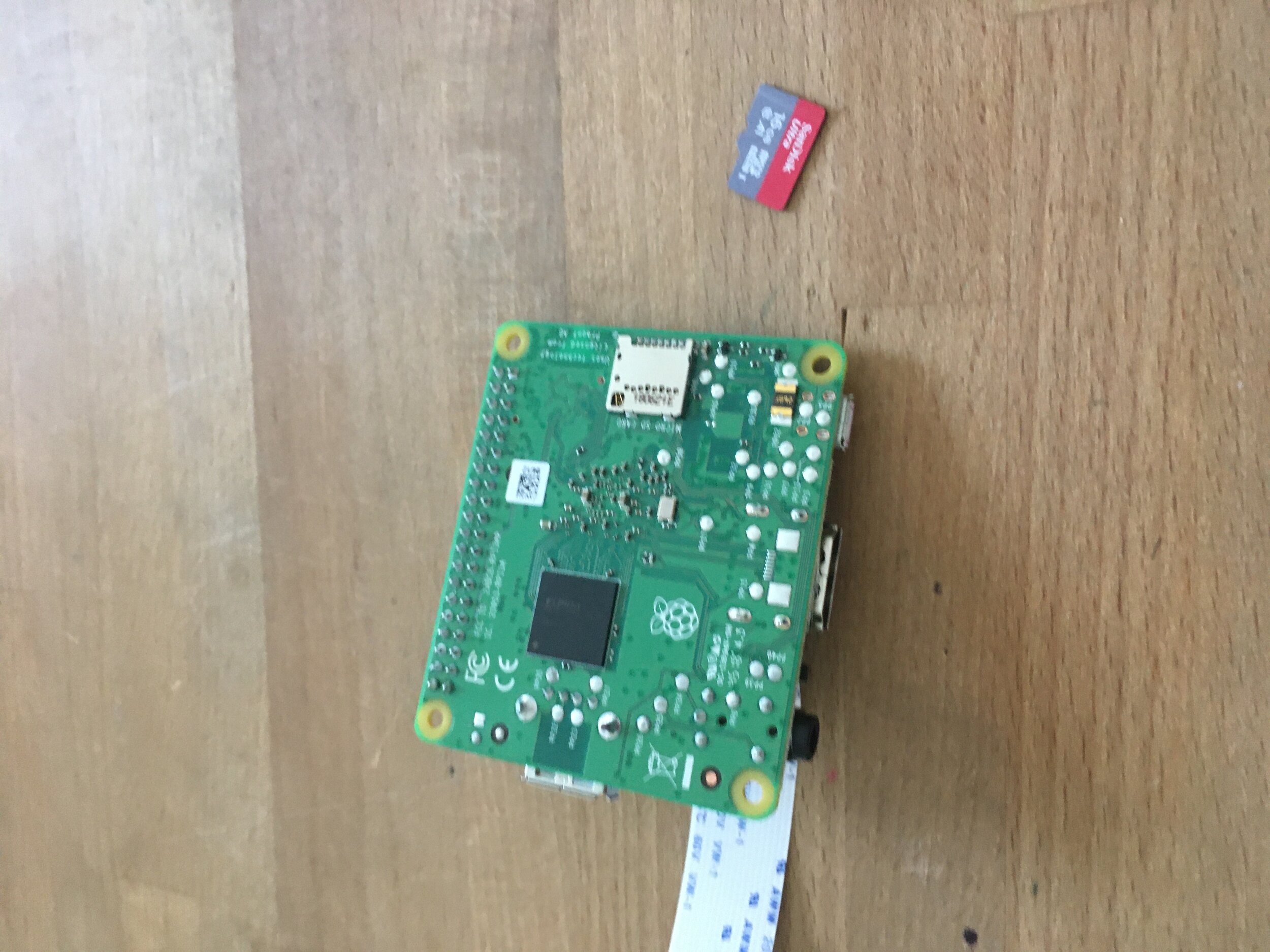
4. Insert the SD Card…

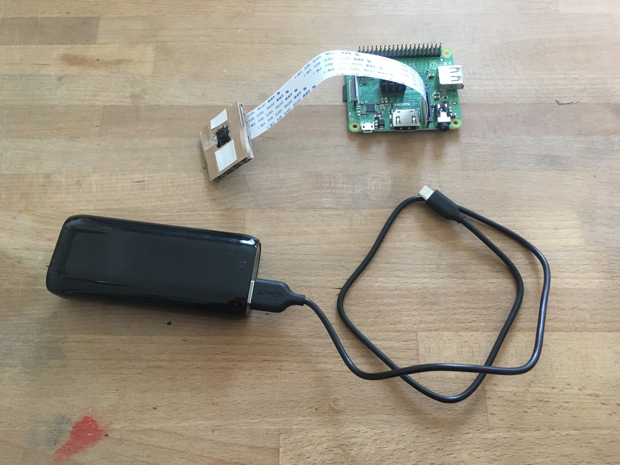
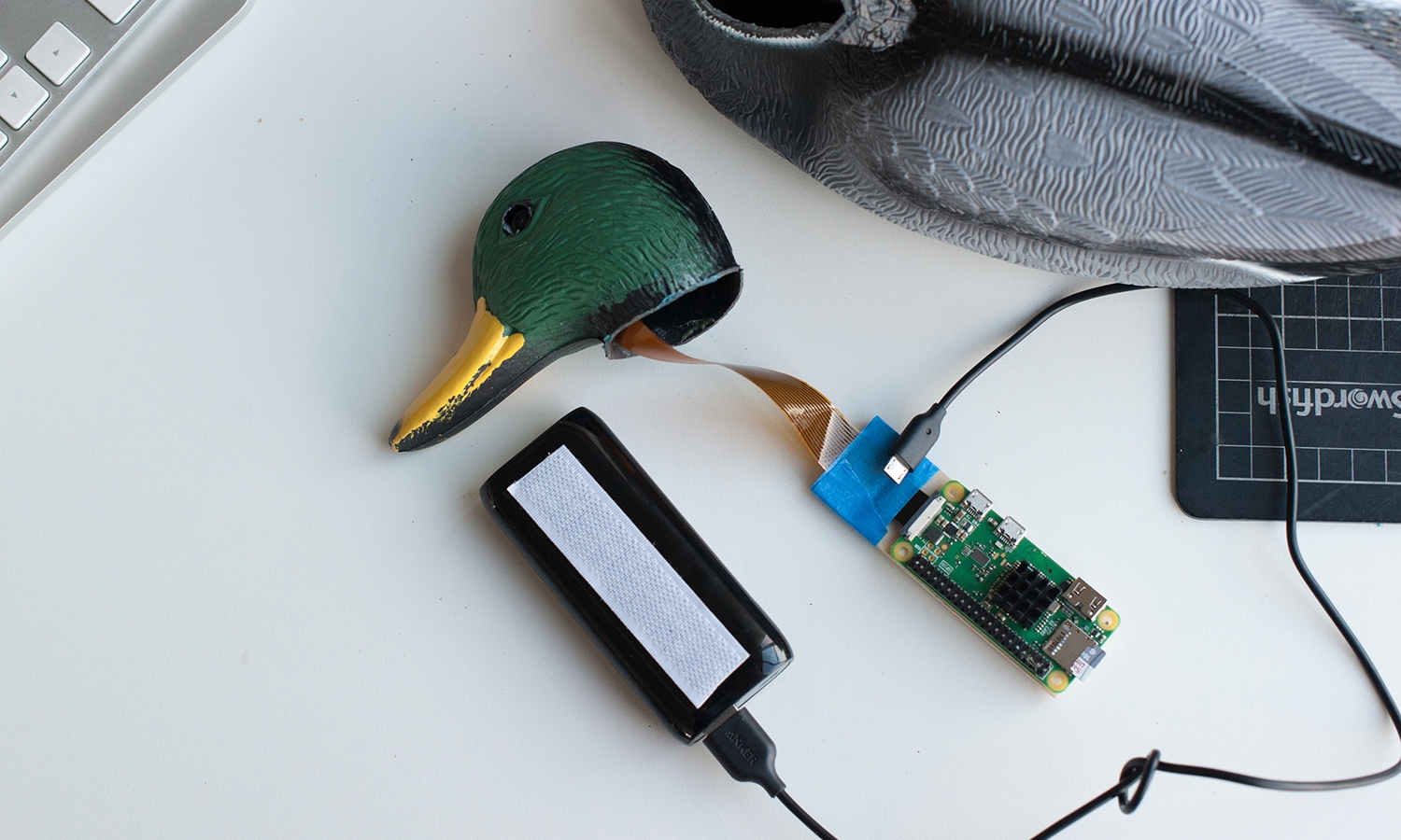
5. Plug in the USB Battery…

10.JPG

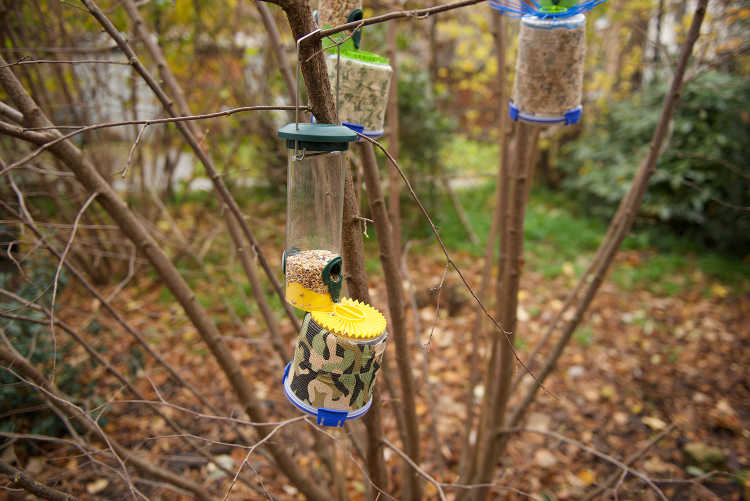
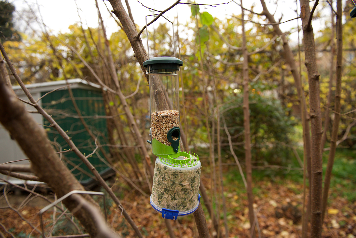
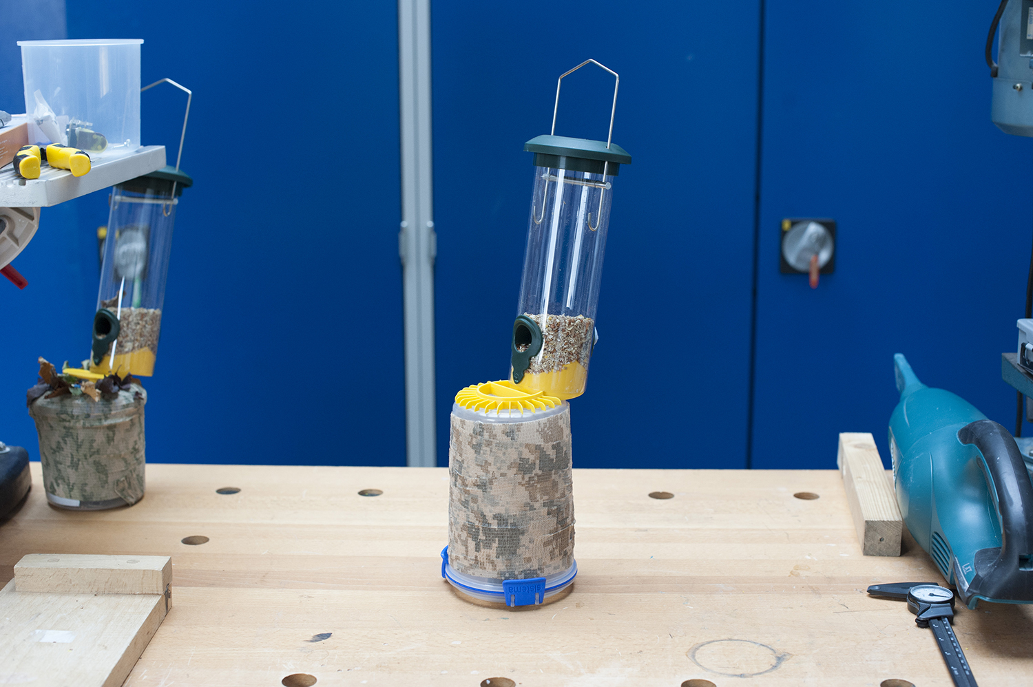
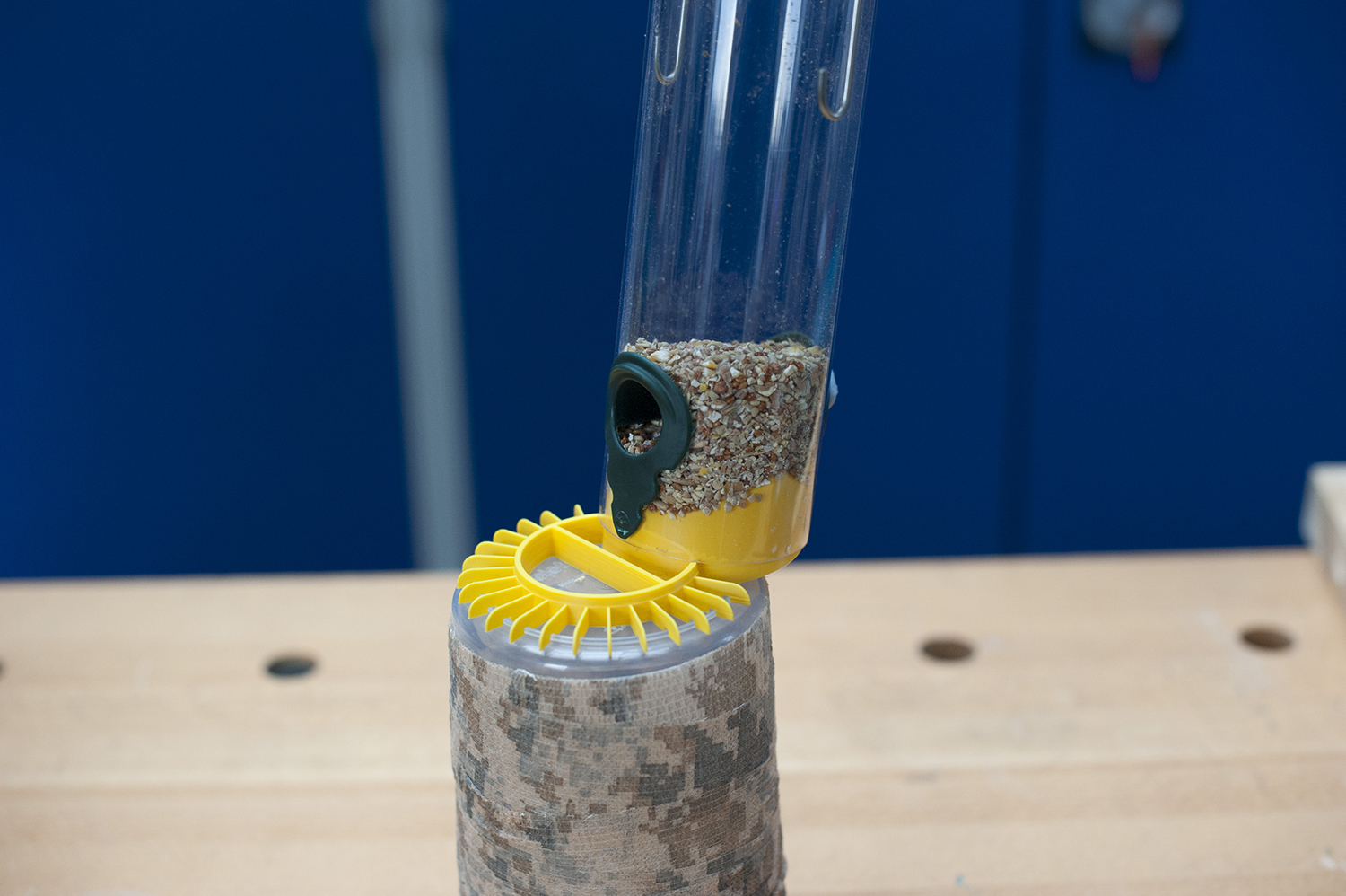
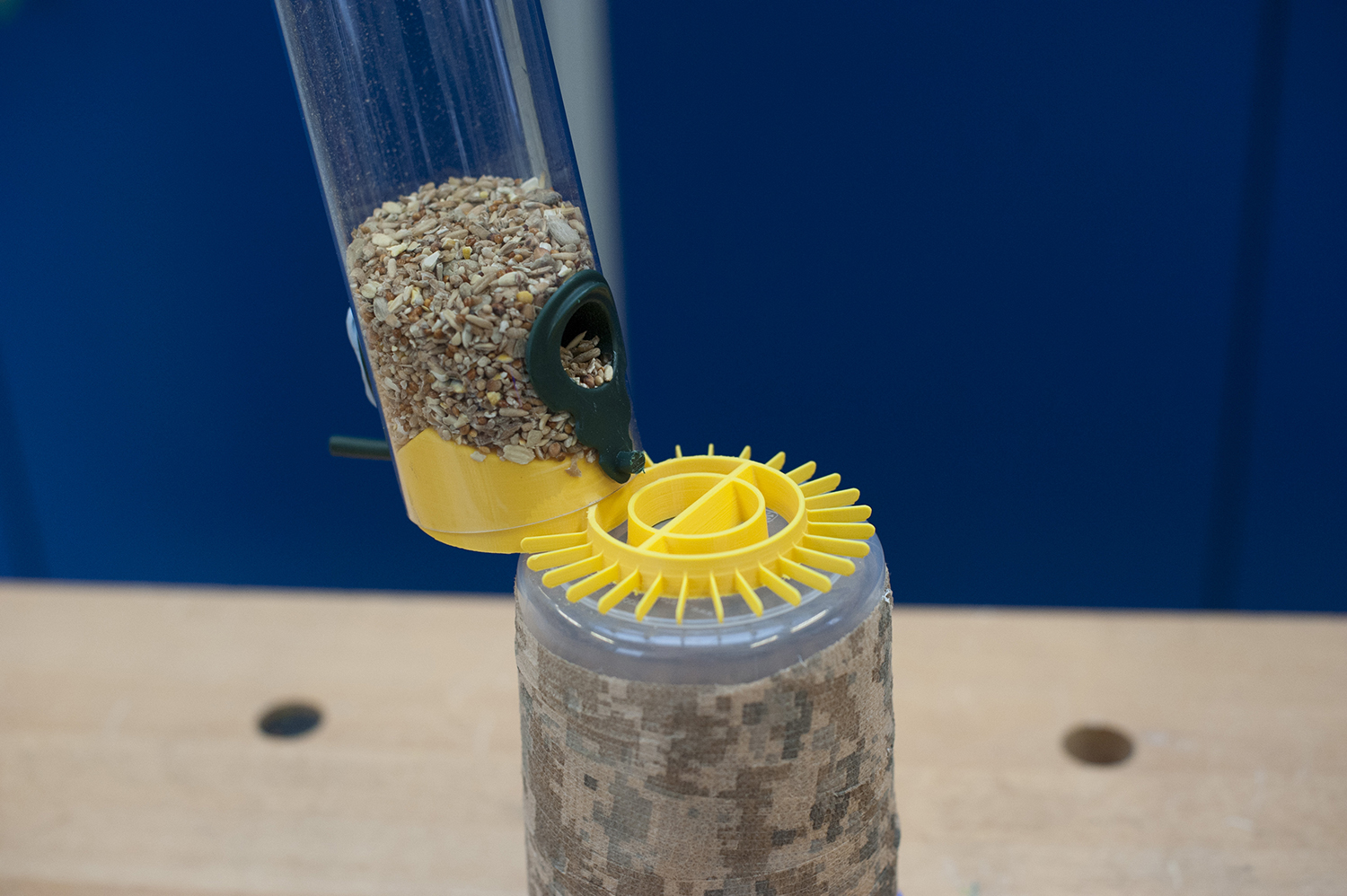
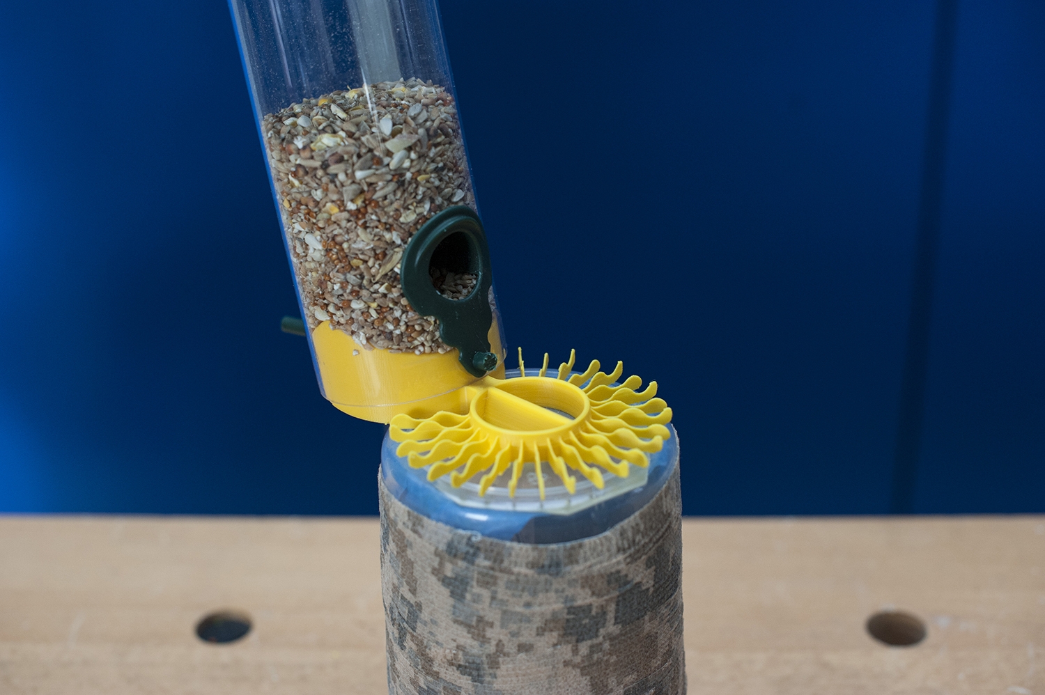
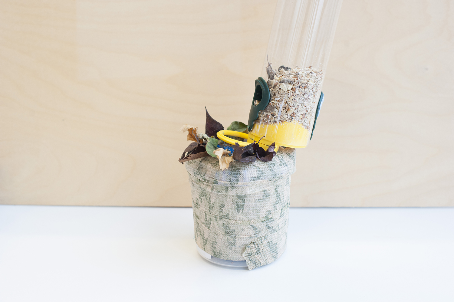
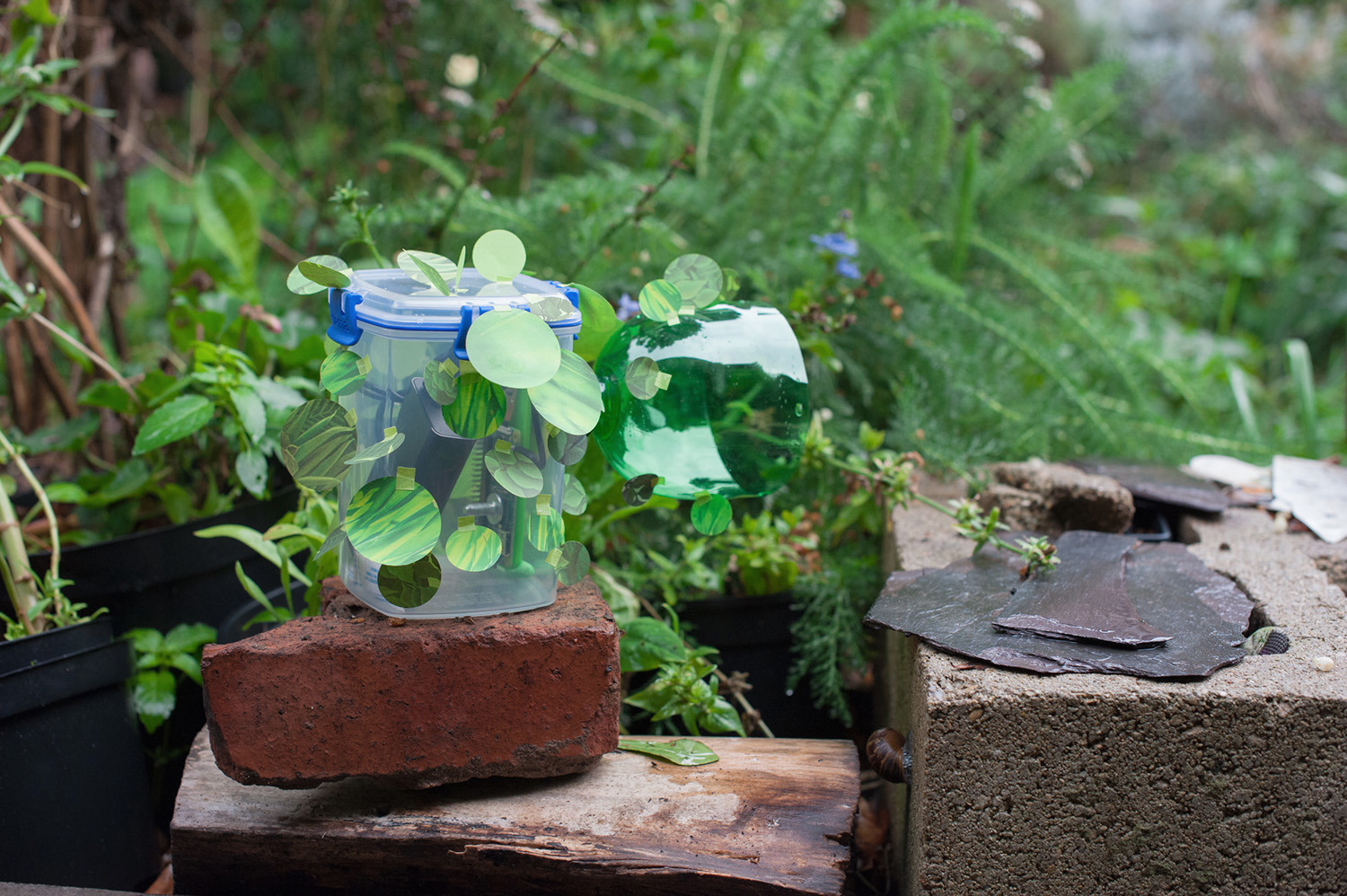
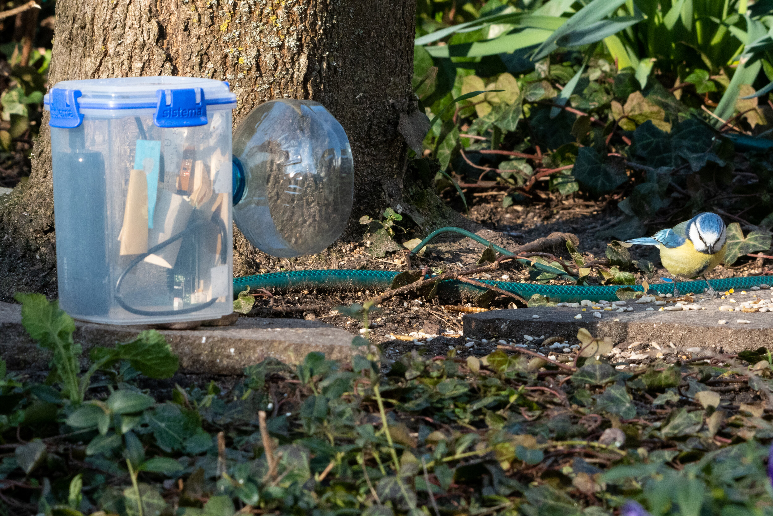
6. Secure the Camera Module to the inside of your food container using sticky tape. The Raspberry Pi and Battery can be left to to move freely within the container.


Animal Animations

A simple and effective way to bring your animal photography to life is to create an animation. We’ve been experimenting with stitching short collections together to turn static moments into compelling micro-narratives.

There are many free online tools that convert images into animations. We’ve found gifmaker.me particularly handy as a way to upload and compose images with basic size, speed and exporting options. As a general rule of thumb between 10 & 30 images is a good number and 350 milliseconds per image gives a satisfying speed. Exporting your animation as a GIF is normally effective, however if you wish to post your animal stories on Instagram then an MP4 format is recommended.

Why not give it a go! and keep us updated on social by using #mynaturewatch

Designing for birds

For our next device we are working on a bird feeder that has RFID technology that can track birds bearing RFID tags. Part of our team has been dedicated to adapt existing birdfeeders to fit the hardware, which consists of a microcontroller, an RFID reader and a PCB inductance coil.

One of our main challenges has been to design a perch that will position the birds inside the reading distance of the coil. The birds need to land within a diameter of 42 mm above the coil, a few millimetres off and the reader will not detect them. The tricky task is to design a feeder that is inviting enough to attract the birds and at the same restricts the area where they land. 

For this purpose, we have been doing some traditional user trials by testing several 3d printed bird feeder adaptors, and the only way to get feedback from our feathered users is by capturing their visits with a Naturewatch camera. The pictures above show the different designs we have developed in use. So far we have managed to get blue tits and robins using the feeders, but we are still working on ways to get them to land in the right spot. 

As expected, squirrels have made an appearance in the hope of getting some food!

We will post more developments soon. Any suggestions or tips for designing for birds will be very welcome, please email us at interaction@gold.ac.uk. 

Camouflage ideas

We have been receiving great pictures from the Naturewatch community showing the different setups people have built for their cameras. Amongst these pictures, we’ve seen some cameras that have been camouflaged using camo tape and army camo netting. We have been playing around with DIY ways to make fake foliage to hide the cameras in the wild. Here are some ideas if you would like to get crafty. 

Make your own foliage by taping green individual ‘leaves’ made out of cut-outs of print greenery. You can use images of bright green grass, paintings of landscapes or any pattern that can resemble forest camouflage. After printing different types of foliage in green card, we cut circles in different sizes. You can use a scalpel or circle cutter to do this or go freestyle to create irregular shapes. We then recreated foliage around the camera by taping the circles individually along the surface. 

After testing the camouflaged camera in our garden we noticed that the leaves are changing colour due to the season so we also made an autumn version of the foliage using red and yellow leaves.

If you would like to try this you can also use old magazines or card packaging with tones of the foliage you would like to recreate. This initial idea works as a temporary camouflage, for more permanent solutions we will experiment with other materials. 

Let us know if you have any ideas for camouflaging your Naturewatch kit by sending us your pictures to interaction@gold.ac.uk 

Building a Duck Cam

We’ve been exploring ways to build a floating camera to document ducks and other water birds in a pond. Using a decoy duck, we built a quick enclosure to test how the ducks would react to a camouflaged camera. 

To make a proper spy camera, the electronics were hidden inside the plastic duck. This required some surgery; we cut the head off with a scalpel to make an opening that would be big enough to fit in the RPi Zero, the power bank and USB cable. One of the eyes of the duck was removed to make a hole for the camera lens, which was fixed from the inside with Blue Tac. We recommend using an adhesive that allows repositioning as the shape of the duck’s eye can make it tricky to have the camera lens in a straight angle. For this version, we used the Raspberry Pi Camera v2.1 as it has a longer cable than the smaller camera module for RPi Zero.

As in our previous cameras, we fixed the RPi circuit board to a rigid base with sticky pads. In this case, we used a square of 3 mm plywood of 30x95 mm. The ribbon cable was held with low tack tape to the plywood board to secure the camera connection. To prevent the components from rattling loose inside the duck, we applied strips of Velcro tape on the base of the inside of the duck to attach the Rpi Zero and power bank.

After all the components were in place, the head of the duck was glued back with a glue gun. For this trial we closed the duck with the camera turned on, as once the duck is glued together is not possible to access it. With a full battery, the camera can work for approximately 8 hours. Once the camera was ready we took it to the local pond in Folkestone Gardens to test it. 

The gallery above shows some pictures of the process of making the Duck Cam, as well as the first results of the test. With the help of some bait (we recommend seeds or food pellets), the ducks approached their plastic friend and we managed to get some shots of them as well as some flying pigeons that wanted to get a share of the food. The camera needs to be repositioned, as the frame of the pictures is not horizontal, so it only captured glimpses of the ducks.  We will work on new iterations to get a better view of life in the pond. 

Stay tuned to find out the results of our next experiments. If you have any stories, tips or suggestions to share with the Naturewatch community please email: interaction@gold.ac.uk 


Cinematic Infrared Lighting

The standard setup of the Raspberry Pi Infrared Camera achieves good functional results at night or in low-light conditions, but with a little time and patience, the infrared LED lights can be separated from the camera and used to light subject more cinematically and remove the night vision red eye effect caused by the light source being next to the camera lens.

The Raspberry Pi Infrared Camera is a package of three PCB's, bolted together to transmit power from the camera module to the each LED light via exposed copper pads on each board. In most cases, these boards are supplied unattached and have to be assembled by the user. Separating the LED lights is therefore straightforward and there are two basic options to power them as movable lights. First, is to solder extension wires to between the exposed copper pads on the PCB's, which has the advantage of retaining a single power (battery) source for the entire camera setup but causes problems in thinking about how to waterproof the tethered lights. The second option, shown below, separates and powers the LED lights independently using rechargeable AA batteries and housed in jam jars.

 The 3 volt output of two AA batteries connected in series (such as the twin battery holder used below) is perfectly adequate to run the LED light for several hours. For all night use, we found it best to have double this capacity by using two, twin battery holders connected in parallel in order to share the load. Building the external light is reasonable straightforward using basic soldering skills.

To simplify the process, try to purchase battery holders that have flying leads already attached. Solder the two ground (black) wires to the ground terminal on the LED light. This isn’t marked, but is on the left, if the board is orientated with the terminals on the bottom and the LED light at the top, facing you. Solder the 3v (red) wired to the other terminal. We found it helpful to add a piece of mirrored card behind the LED to help focus the light, but this isn’t necessary. The battery packs and LED then can be mounted in any suitably sized, clear, jam jar.

Experiment with lighting position, to the side of the subject looks good (as with the images of the fox below) but there are many combinations. Also try adding other infrared light sources, old TV remote controls are a great source of redundant infrared LED’s.

If you have any hints, tips or stories that you would like to share with the My Naturewatch community through this blog, please email: interaction@gold.ac.uk